Schematics
MY84-85
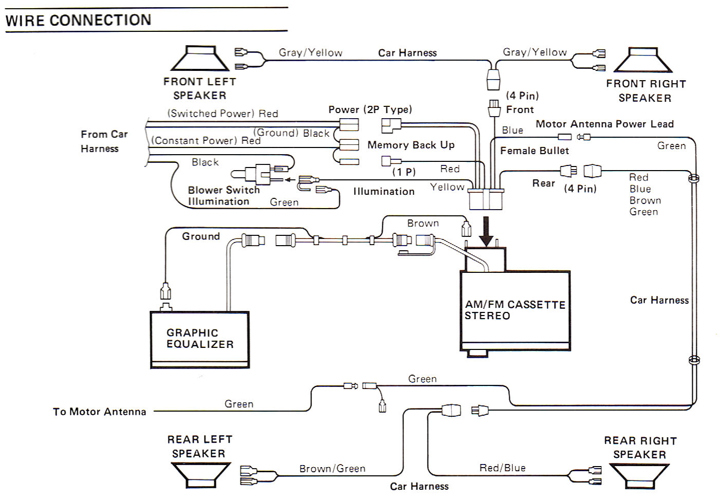
The first generation of Saab Clarion Audio System with Graphical Equalizer was installed in Classic 900
on MY84-85. Amplifier was built into the headunit and Graphical Equalizer was connected the headunit
using a DIN-cable. More detailed headunit specification was be found under Manuals & Broschures.
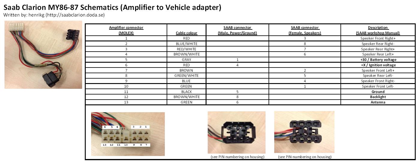
MY86-87
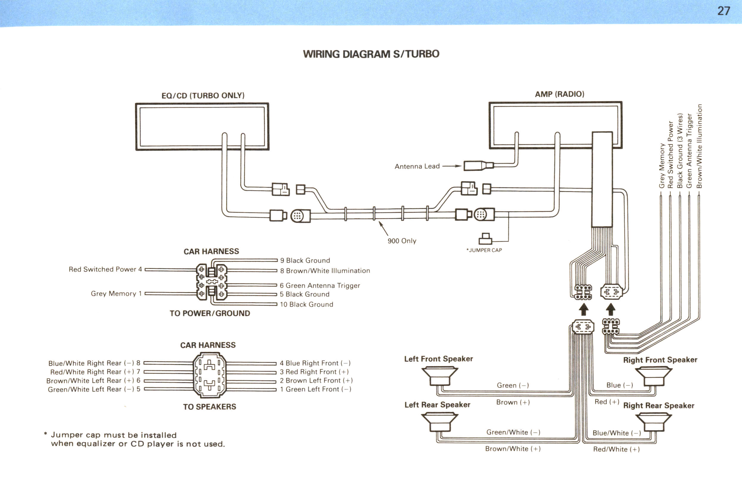
(S/Turbo) In the second generation the headunit was not equipped with any amplifier. If the vehicle was
equipped with an equalizer (Turbo models) the sound was sent from the headunit to the equalizer and
back to the headunit thruh a 13-pin DIN-connector. If the vehicle was not equipped with an equalizer a
jumper-cap was needed instead. Finally the audio was sent from the headunit to amplifer thruh another
13-pin DIN-connector. Vehicles without EQ still needed the external amplifier and these vehicles was
equipped the amplifier mounted behind a storage-box, see Components MY86-87 section.
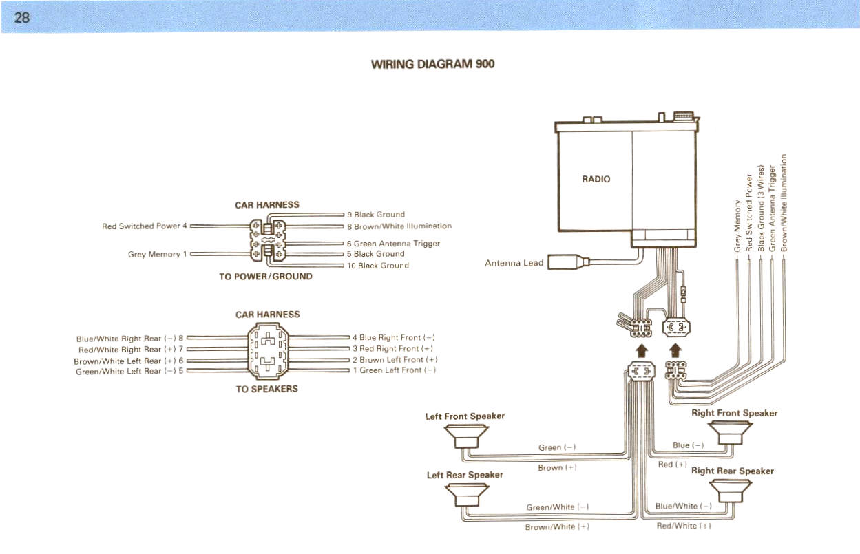
(900) The low-end version is standalone with an amplifier built into it and could not be connected to
any equalizer.
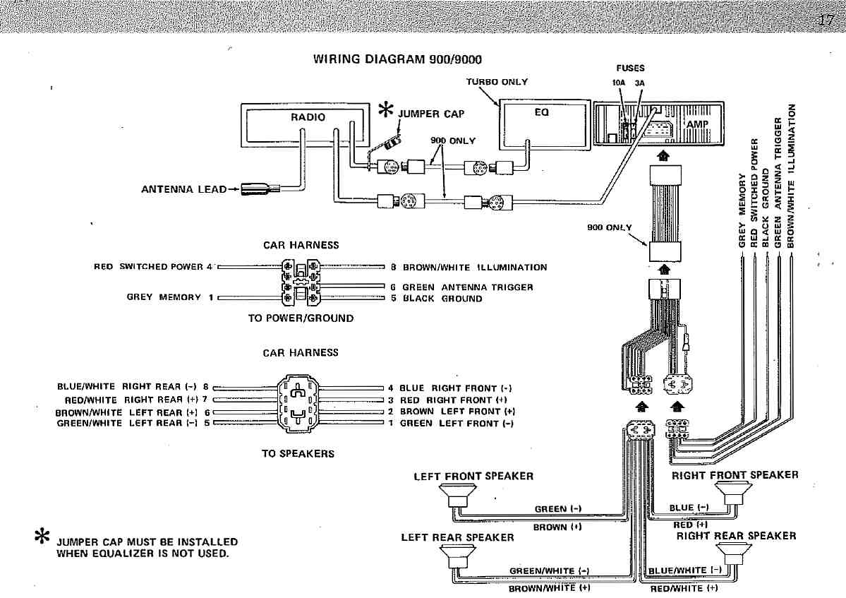
900:
MY88-91
(S/Turbo + 900 MY89-91) In the third generation the amplifer was (again) integrated into the head unit
and an optional CD-player was introduced. If vehicle was equipped with an equalizer or CD-player
(Turbo) a 12-pin DIN-connector was used together with additional grounding wires (Note: Not the same
pin-configuration as the second generation). When equalizer/CD-player was not used an jumper-cap is
needed here aswell. With a special Clarion DIN Y-cable it was possible to connect all the units
(Headunit -> CD-player -> Equalizer -> Headunit), it is important to connect the units the correct order to
get it working. This setup was only used on Saab 9000 which had the space for three DIN-units.
(900 MY88) The low-end version is carry-over from MY86-87 which is standalone with an amplifier
built into it and could not be connected to any equalizer.
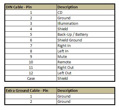
900 MY88:
Here is detailed information of the DIN-cables pinning:
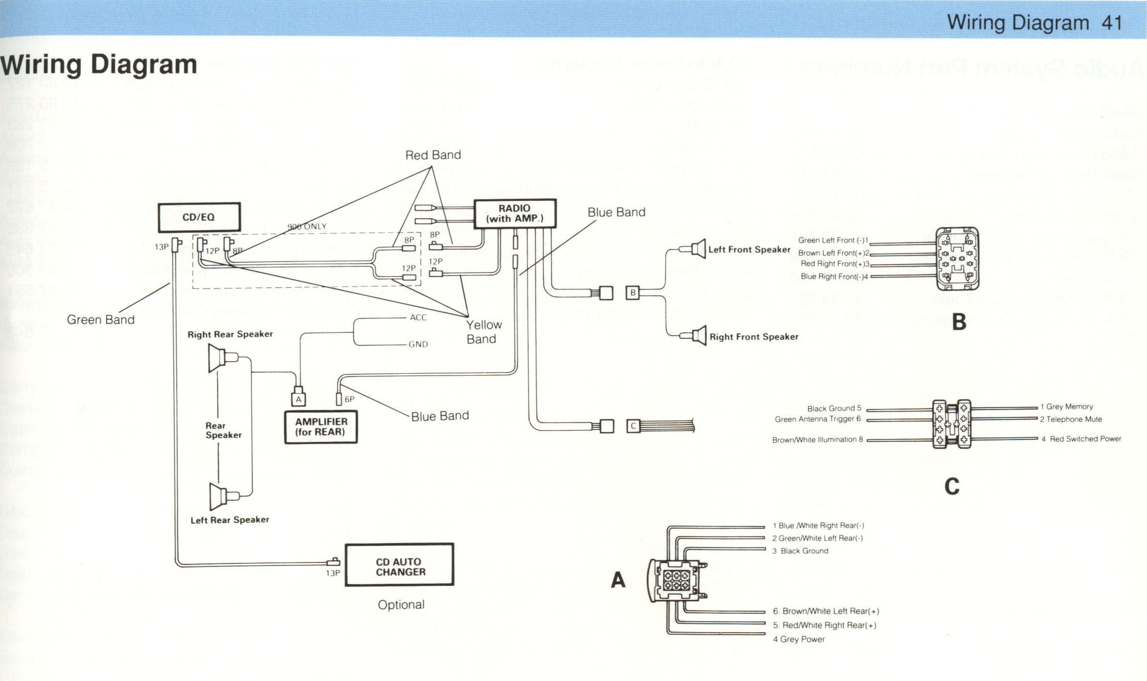
MY92-94
In the forth generation a combined EQ-CD unit was introduced aswell as a CD-changer and a separate
amplifer which only powered the rear left/right speakers. An amplifier for the front left/right speakers was
located inside the head-unit. If vehicle was equipped with an EQ or an combined EQ-CD, then it was
connected with the headunit using the red (8-pin) and the yellow (12-pin) DIN-connectors (if not,
a jumper cap had be to installed on the red connector).
The rear amplifer was connected to the headunit using the blue 6-pin DIN-connector.
A CD-changer was possible to have in the trunk, but required the vehicle to also be equipped with a
EQ or the combined EQ-CD. The CD-changer was of model Clarion CDC-635 (to be verified) and
connected to the EQ/EQ-CD using the green 13-pin DIN-connector. The CD-changer uses the Clarion
C-bus protocol to communicate with the EQ/EQ-CD unit.
Here is detailed information of the DIN-cables pinning:
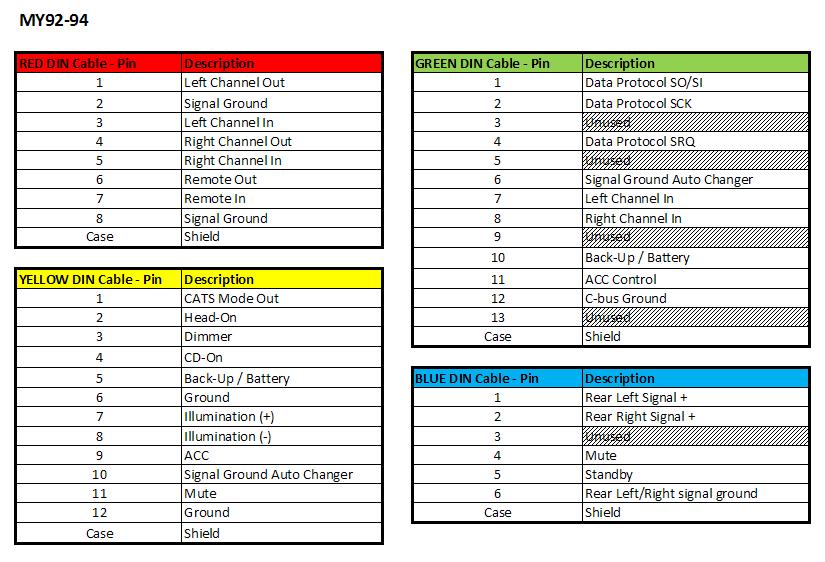
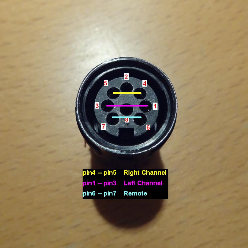
If Jumper-cap is needed but you dont have one, here is the pin-out. Three short-circuits are inside
the jumper: Pin4-5, Pin1-3 and Pin6-7.